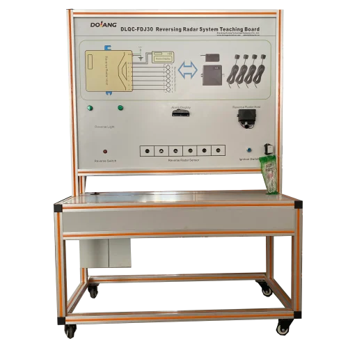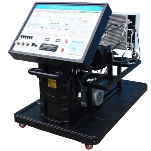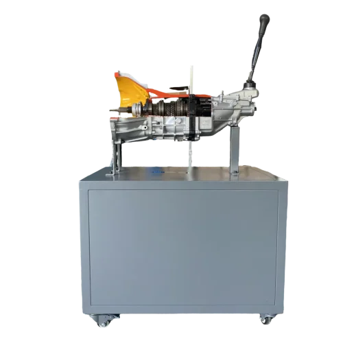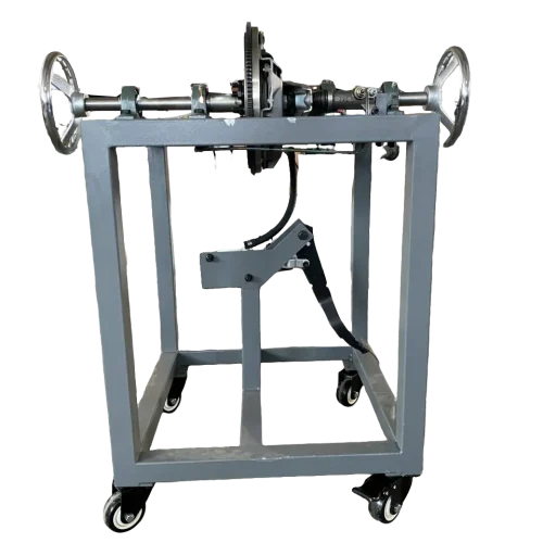

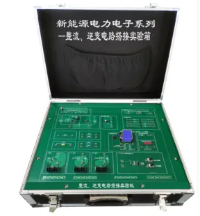
- I. Product features
- Experimental components and modules are installed on the PCB board of the training box. According to the provided instructions, it can be directly connected to the jack on the module, and one-to-one correspondence between the schematic diagram and the actual connection can be achieved. This design enhances understanding, participation, and actual participation.
- All component components are placed in a sturdy module with a plug-in wiring socket, which can be upgraded or more complex circuit components can be added in the future.
The product uses mainstream market components compatible with various standard electrical instruments, and can form various basic circuits used at the technical level.
II, the functional characteristics.
A plug-in connection system with unified specifications is adopted, and the colors are distinguished for easy identification. The socket is equipped with a hollow rivet jack, which can achieve smooth plug-in and unplugging operation. Direct plug-in connections ensure that circuit nodes maintain equal potentials, simplify troubleshooting and provide a clear and intuitive understanding of circuit operation.
If the component is damaged due to an operational error, it can be easily replaced, thereby significantly improving reusability and long-term value.
III. Equipment composition
- The equipment supports the construction of multiple functional circuits in accordance with the training requirements, and each functional circuit can be operated and demonstrated normally during the guidance period.
- The support board is made of a special PCB board arranged in a rectangular format, with a size of not less than 30cm×30cm and a thickness of at least 1.6mm to ensure durability during repeated use and multiple plug inserts.
- The overall design adopts a high-strength aluminum box structure, the size is not less than 35 cm×35 cm, and the reinforced frame. It features a flat hinge design that allows both sides to open. The interior is lined with black velvet fabric and includes a sewn pocket for organized component storage.
- The connecting cable is made of environmentally friendly materials and is equipped with plug-in terminals for easy and reliable connection on the universal board.
- Provide a comprehensive training manual with printed and digital high-definition versions. It guides students step by step through circuit assembly and experiments. manual
- 6. It includes product description, physical structure diagram, operation guidance, connection exercises and detailed explanation of working principles.
IV, the training function
- DC half-wave rectifier circuit connection
- Single-chip full-wave rectifier circuit connection
- Chip-based full-wave rectifier circuit connection
- Single transformer and transistor inverter circuit connection
- Circuit connection of chip-controlled inverter
- Single-tube field effect transistor (FET) inverter circuit connection
- Basic experimental circuit
- Construction and testing of a single-resonance half-wave rectifier circuit using capacitors and diodes:
- Construction and testing of a single-resonance full-wave rectifier circuit using capacitors and diodes:
- Construction and testing of pwm-controlled full-wave rectifier circuit using mainstream rectifier chip:
- Construction and testing of single transformer and transistor inverter circuit:
- Chip control inverter circuit construction and testing:
- Construction and testing of a single-resonance inverter circuit using diodes, capacitors and field effect transistor:
- Basic Configuration
| Serial number | Name | Qty. | Unit |
| 1 | Training box | 1 | |
| 2 | Electronic PCB board | 1 | Set |
| 3 | Manual | 1 | Set |
| 4 | Connection Cables | 10 | Pcs |